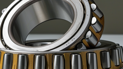
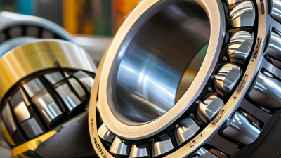
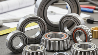
A Tapered Roller Bearing uses conical rollers running between matching inner and outer raceways. The angled contact surfaces help it support both radial loads and axial loads. In many designs, however, axial load capacity is strongest in one direction. Paired bearings are often used when forces act both ways.
The geometry matters. A truck wheel hub, gearbox, or machine-tool spindle may face changing loads, vibration, and heat during operation. Correct bearing selection can help maintain smooth rotation and manage those forces. Small component, significant job. Yet performance depends on more than the bearing’s shape: shaft alignment, mounting fit, lubrication, and operating conditions all play a part.
This guide explains the bearing’s main components and how tapered rollers carry loads. It also looks at common applications, material and design considerations, and practical selection factors such as load rating and speed. Installation deserves attention, too. Incorrect adjustment can lead to excess heat, noise, or premature wear, even when the bearing itself is suitable.
A specification sheet is useful, but it cannot describe every real operating condition. That is an easy detail to overlook. The right choice should be checked against the equipment maker’s requirements and the actual load, speed, and environment. With that context, readers can better understand where a Tapered Roller Bearing fits—and where another bearing arrangement may be more appropriate.
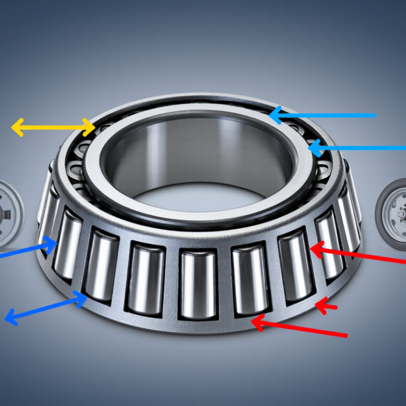
A tapered roller bearing contains rollers shaped like truncated cones, set between an inner raceway and an outer raceway. Their sloping surfaces match the angled raceways, so the rollers sit in a ring rather than rolling on flat tracks. The roller, raceway, and bearing axis are designed around a shared geometric apex. That detail matters. It helps the rollers roll with little sliding instead of scrubbing heavily as they turn.
The angled contact lines let the bearing support radial loads and axial loads at the same time. In a simplified diagram, contact may look like a clean line along each roller. Under load, elastic deformation spreads that contact into a narrow area. A neat drawing can hide this. In an actual assembly, shaft alignment, internal clearance, and manufacturing tolerances affect how evenly the rollers share force. Even slight misalignment can concentrate load near a roller’s edge. The geometry is elegant, but it is not self-correcting. A bearing that looks properly seated may still run hot if its adjustment is off.
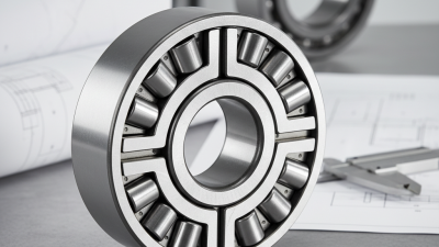
A tapered roller bearing supports radial load and axial load through angled contact between its rollers and raceways. The rollers are shaped like truncated cones, and their surfaces meet the raceways along sloped contact lines. That geometry helps carry forces acting across the shaft and forces pushing along it.
The contact angle determines how the load is shared. A steeper angle generally increases axial load capacity, while the bearing’s size, material, lubrication, and operating conditions also matter. Not every tapered roller bearing handles the same combination of forces. Under load, the rollers transfer force through the raceways into the housing and shaft. The action is not perfectly simple: friction and heat rise if lubrication is poor or alignment is off.
Direction matters. A single bearing usually supports axial force mainly in one direction, so paired bearings are often used when thrust can reverse. Installation also requires care. Excessive preload can create heat; too much clearance may allow shaft movement. During inspection, uneven roller marks or unusual warmth can signal a problem, but neither clue alone confirms the cause. Measurements and operating conditions should be checked before adjusting the assembly.
A tapered roller bearing uses two matched surfaces: the cup, or outer race, and the cone, which holds the inner race and rollers. The rollers taper toward a shared point on the bearing axis, helping the assembly carry both radial and axial loads. The cup usually sits in the housing; the cone fits on the shaft. Together, they guide rolling contact under load. Small details matter. A burr on a shaft shoulder or a cup that is not fully seated can distort the setup and affect readings.
Clearance is the small amount of internal movement before the rollers are firmly loaded. Preload removes that free movement by applying a controlled force through the bearing arrangement. Too much preload can increase friction and heat; too little may allow movement, noise, or uneven wear. There is no universal adjustment value: shaft fit, temperature, load, and the equipment maker’s specifications all matter. A dial indicator can help measure end play, while careful rotation can reveal rough spots. Check the assembly method, too. It is easy to mistake a smooth hand feel for correct preload, especially before the bearing warms during operation.
What Is a Tapered Roller Bearing?
ISO 281 Rating Life: L₁₀ = (C/P)^(10/3) for Roller Bearings
A tapered roller bearing uses angled rollers and raceways to carry radial loads and axial loads in one direction. Its geometry makes contact conditions sensitive to alignment and adjustment. In service, a mechanic might check end play while turning a shaft by hand; a small setup error can affect heat and wear.
ISO 281 estimates basic rating life with L₁₀ = (C/P)^(10/3) for roller bearings. C is the bearing’s basic dynamic load rating, while P is the equivalent dynamic load in operation. The result is expressed in millions of revolutions. If C is three times P, the estimate is about 39 million revolutions. That matters.
L₁₀ represents the life that 90 percent of a sufficiently large group of similar bearings is expected to reach or exceed under defined conditions. It is not a promise for an individual bearing. Real results also depend on lubrication, contamination, mounting, and load variation. The neat equation can mislead when those details are ignored. For a sound estimate, use the correct operating load and treat the rating life as a planning tool, not a calendar deadline.
This chart illustrates the basic rating life for a roller bearing with a dynamic load rating (C) of 50 kN. L₁₀ is shown in millions of revolutions and is calculated using the ISO 281 roller-bearing exponent of 10/3. As equivalent dynamic bearing load (P) increases, calculated rating life decreases. These illustrative values are not product specifications; actual life depends on operating conditions and other factors.
ISO 355 Dimensions and Common Uses in Axles, Gearboxes, and Hubs
A tapered roller bearing uses conical rollers and matching raceways to carry radial and axial loads together. Its geometry helps keep the rollers guided under load. ISO 355 specifies metric boundary dimensions and series designations, helping engineers match bearing sizes to shaft and housing layouts. It does not, by itself, determine load capacity or service life. Those depend on operating conditions, materials, lubrication, and mounting.
In vehicle axles and wheel hubs, paired bearings support cornering forces and help control shaft movement. Gearboxes use them where shafts face combined loads and accurate alignment matters. Small setup errors can still cause heat, noise, or uneven raceway wear.
ISO 281:2007 defines basic rating life, L10, as the life that 90% of a sufficiently large group of apparently identical bearings can reach or exceed under stated conditions. That is a statistical rating, not a promise for every installation. Fit, preload, contamination, and lubricant condition can shift real service life considerably.
A clean assembly matters. So does checking endplay after installation.