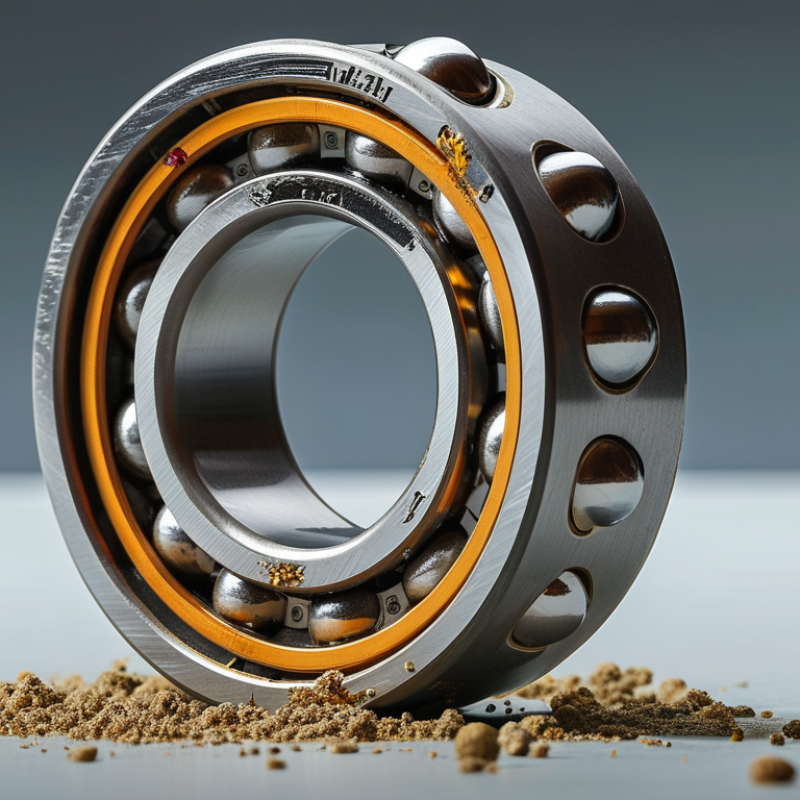
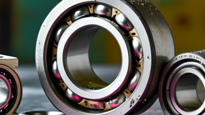
A Double Groove Ball Bearing is designed to guide rotating shafts while carrying radial loads with controlled friction. Its two distinct grooves can support paired contact points, improving stability in compact assemblies. The exact meaning varies across suppliers, however. Some describe a two-row bearing, while others mean two groove profiles within one ring.
That distinction matters. A wrong interpretation can change load capacity, clearance, sealing, and service life. SKF’s Rolling Bearings Catalogue explains that internal clearance, lubrication, alignment, and operating temperature strongly influence bearing performance. Timken’s Engineering Manual likewise connects bearing life with load, speed, mounting accuracy, and contamination control. These are practical concerns, not catalogue decoration.
ISO 281 provides the widely used method for calculating basic rating life. It also reminds engineers that calculated life is not a guarantee of field performance. Dust wins sometimes.
Bearing specialist Tedric A. Harris wrote, “Rolling bearings are machine elements that permit relative motion between two parts while carrying load.” That simple statement captures the core function of a Double Groove Ball Bearing. The bearing must move smoothly, but it must also resist vibration, heat, and uneven loading.
Industry market analyses from Grand View Research and Fortune Business Insights identify automation, electric motors, and precision machinery as major demand drivers for ball bearings. Yet market growth does not remove engineering uncertainty. Shaft fit, housing rigidity, grease selection, and installation tools still determine the result.
This guide examines construction, operating principles, load behavior, applications, and selection criteria. It also questions a common assumption: more grooves do not automatically mean better performance.
What Is a Double Groove Ball Bearing?
A double groove ball bearing supports radial loads and limited axial loads through rolling contact. The term can be confusing. In many catalogs, it describes a double-row deep-groove bearing, not two grooves on one side. Its basic structure includes an inner ring, outer ring, rolling balls, and a cage. Two parallel ball rows share the load. Each row runs inside its own raceway groove. This arrangement increases radial capacity within a compact housing.
The rings guide rotation, while the cage keeps balls evenly spaced. Seals or shields may protect the raceways from dust and retain lubricant. ISO 281 provides methods for calculating bearing life, but field life often differs. Misalignment, contamination, and poor lubrication remain difficult variables. The U.S. Department of Energy’s Motor Systems Market Assessment reports that motor systems consume about 46% of manufacturing electricity in the United States. Small bearing losses can therefore matter across many machines. The structure looks simple. Its operating conditions are not.
Tips: Check the catalog definition before choosing a bearing. Confirm whether “double groove” means double-row construction. Match the load rating with ISO 281 data. Inspect the shaft and housing fits carefully. Excessive preload creates heat. Insufficient preload can create vibration. In practice, lubricant selection is easy to underestimate. A clean installation may matter more than a higher nominal rating.
What Is a Double Groove Ball Bearing?
How Double Groove Ball Bearings Distribute Radial and Axial Loads
A double groove ball bearing uses two raceway grooves to guide its rolling elements. In many designs, two rows of balls share the load. This structure increases radial capacity compared with a single-row bearing of similar outside diameter. It also supports axial loads from both directions, although capacity depends on the groove profile, contact angle, and internal clearance.
Radial force acts toward the shaft center. The two ball rows divide this force through separate contact paths. Axial force moves along the shaft. Each groove then carries part of the thrust through angled contact between the balls and raceways. Load sharing is rarely perfectly equal. Shaft deflection, housing distortion, contamination, and misalignment can shift more force to one row. That detail is often overlooked.
ISO 281:2007 defines basic rating life as L10 life. It means 90% of identical bearings should reach or exceed the stated life under controlled conditions. Real machinery can perform differently. Lubrication and installation remain decisive.
Tips: Check the manufacturer’s radial and axial ratings together. Do not add them directly. Measure shaft fit and housing alignment before installation. A quiet bearing is not always a healthy bearing. Track temperature, vibration, and grease condition during operation. My practical view is simple: load distribution should be verified, not assumed.
A double-row deep-groove ball bearing uses two rows of balls and two corresponding raceway grooves to support radial loads and axial loads in both directions. Actual capacity depends on bearing geometry, internal clearance, speed, lubrication, mounting accuracy, and operating temperature.
| Load or Design Dimension | How the Load Is Transferred | Distribution Between the Two Rows | Engineering Relationship or Data | Practical Design Considerations |
|---|---|---|---|---|
| Radial load | The shaft load acts perpendicular to the bearing axis. The inner ring transfers the load through the balls to the outer-ring raceways. | Both ball rows normally carry radial load. The loaded zone contains the balls closest to the radial load line; balls outside this zone carry little or no load. | For a centered bearing under a predominantly radial load, the equivalent dynamic load is commonly represented as P = Fr. |
Radial load sharing is not automatically exactly 50/50. Shaft deflection, housing distortion, clearance, and misalignment can cause one row to carry more load. |
| Axial load in one direction | An axial force creates an angle between the contact force and the bearing axis. The raceway shoulders and ball contacts react to the thrust load. | Both rows can contribute, but the row with the more favorable contact orientation may carry a larger portion of the axial force. | For combined loading, catalog calculations commonly use P = XFr + YFa, where X and Y depend on bearing geometry and the axial-to-radial load ratio. |
Use the manufacturer’s rating factors for the selected bearing series. The equation is not a universal fixed-load split. |
| Axial load reversal | When thrust reverses direction, the opposite raceway contact region becomes the primary load-carrying region. | The two rows continue to share the load according to the new contact conditions, clearance, and elastic deformation. | Double-row deep-groove designs can support axial loads in both directions, subject to the applicable axial-load rating. | Frequent reversals require suitable lubrication, accurate fits, and verification of fatigue life and heat generation. |
| Combined radial and axial load | The radial and axial components create an oblique resultant contact force at the ball–raceway interfaces. | Both rows usually participate, but unequal deformation or preload can make the load distribution asymmetric. | Dynamic equivalent load is evaluated with P = XFr + YFa. Static safety is checked separately using the static equivalent load. |
Do not select a bearing using radial capacity alone when axial force is significant. |
| Static load capacity | Static capacity concerns permanent indentation at the most heavily loaded ball–raceway contact while the bearing is stationary or moving slowly. | The most heavily loaded row and contact can govern the static condition, even if the average load appears evenly distributed. | Static safety factor is commonly expressed as s0 = C0 / P0, where C0 is basic static load rating and P0 is static equivalent load. |
Use a higher safety factor for shock, vibration, low-speed oscillation, or applications where noise and torque must remain low. |
| Dynamic load capacity | Dynamic rating relates to rolling-contact fatigue during continuous rotation under a defined load. | Load sharing between rows affects the stress history of each row; unequal sharing can reduce the effective life compared with an ideal equal split. | For ball bearings, rating life is commonly calculated as L10 = (C/P)^3 million revolutions, where C is basic dynamic load rating. |
The cube relationship means a modest reduction in equivalent load can substantially increase calculated rating life. |
| Internal clearance | Clearance allows rolling elements to rotate freely before operating temperature and fits reduce the running clearance. | Excessive clearance can concentrate load in fewer balls and reduce axial stiffness. Excessive preload can also concentrate load and increase friction. | Operating clearance is affected by the bearing’s initial clearance, shaft and housing fits, temperature difference, and thermal expansion. | Select clearance based on fits, temperature, speed, and misalignment. Avoid assuming that zero clearance gives the best load distribution. |
| Contact angle | A larger contact angle generally improves axial-load capability because a greater component of the ball contact force acts along the bearing axis. | Contact-angle geometry influences how each row reacts to radial and axial forces. | Axial capacity generally increases as contact angle increases, while radial capacity and high-speed suitability may change. | Use a bearing geometry intended for the actual radial-to-axial load ratio rather than relying only on the number of ball rows. |
| Moment or overturning load | An overturning moment produces different radial reactions at opposite sides of the bearing. | The row spacing helps resist the moment by creating a reaction couple. A wider effective spacing generally improves moment resistance. | Moment loading is not represented adequately by a single radial force at the bearing center; reaction forces and contact stresses must be evaluated. | For high moments, use a paired-bearing arrangement or a bearing type specifically rated for moment stiffness when appropriate. |
| Misalignment | Angular misalignment changes the contact pattern between balls and raceways. | One row may become more heavily loaded while the opposite row unloads, increasing local stress and reducing fatigue life. | Double-row deep-groove bearings generally tolerate only limited misalignment; allowable values depend on internal design and operating conditions. | Control housing bore alignment, shaft runout, mounting squareness, and deflection. Do not use this bearing as a substitute for a self-aligning design. |
| Rotational speed | Speed increases centrifugal effects, lubricant churning, heat generation, and cage stresses. | Uneven row loading can produce uneven temperature and wear, especially when lubrication is marginal. | Limiting speed depends on bearing size, cage design, load, lubrication method, sealing, and heat dissipation. | Use the lower applicable speed limit when grease, seals, heavy axial load, or elevated temperature is present. |
| Lubrication | A lubricant film separates the rolling contacts and reduces friction, wear, and heat generation. | Poor lubricant distribution can affect one row more severely, particularly in vertical, oscillating, or high-speed arrangements. | Grease quantity, viscosity, base oil, relubrication interval, and operating temperature must match the application. | Too much grease can raise temperature; too little or degraded lubricant can cause metal-to-metal contact and premature fatigue. |
| Illustrative load example | Assume an application produces a radial load of 2.0 kN and an axial load of 0.6 kN. | The exact row-by-row split cannot be calculated without bearing geometry, clearance, stiffness, and mounting data. | If the applicable factors are X = 0.56 and Y = 1.60, then P = 0.56(2.0) + 1.60(0.6) = 2.08 kN. |
The values of X and Y are illustrative calculation inputs, not universal constants. Use the selected bearing’s published factors for final design. |
| Primary advantages | Two rows of rolling elements provide more load-carrying contacts than a comparable single-row arrangement. | The rows share radial and bidirectional axial loads within the limits of their internal geometry and operating conditions. | Typical benefits include increased radial capacity, improved axial-load capability, and greater stiffness than a comparable single-row bearing. | These benefits may be offset by greater width, higher friction, increased sensitivity to misalignment, and more demanding mounting requirements. |
Note: Load ratings, equivalent-load factors, limiting speeds, internal clearances, and allowable axial loads vary by bearing size and internal design. Final selection should be based on the technical data for the specific bearing configuration.
What Is a Double Groove Ball Bearing?
Key Design Features and Operating Principles
A double groove ball bearing uses two raceway grooves to guide rolling elements between inner and outer rings. In many applications, this term describes a double-row arrangement. Two ball rows share the radial load and improve support against moderate tilting moments. The exact meaning should be checked in the drawing or specification. That distinction matters.
The bearing’s hardened rings provide smooth tracks for the balls. Separators maintain even spacing and reduce ball-to-ball contact. Seals or shields help retain grease and limit dust entry, although they cannot prevent contamination forever. During rotation, the balls roll through the grooves instead of sliding continuously. This reduces friction, heat, and energy loss. Proper internal clearance allows expansion during operation and prevents excessive preload.
Load distribution depends on alignment, speed, lubrication, and shaft stiffness. A double-row design can handle radial forces from several directions, but it is not automatically suitable for heavy axial loads. Installation also matters. Pressing through the wrong ring can damage the raceway before service begins. Small details matter. In field inspections, unusual noise, rising temperature, or rough rotation often signals contamination, misalignment, or insufficient lubrication. However, noise alone is not a complete diagnosis. A careful technician should compare operating conditions with manufacturer-independent bearing calculations and measured data. The design appears simple, yet its reliability depends on many connected choices.
Key design features and operating principles
A double-groove, commonly double-row, ball bearing uses two parallel ball-and-raceway sets. Compared with a single-row design, the paired rows provide two radial load-carrying rows and two corresponding inner- and outer-raceway groove sets. Deep-groove geometry can also support axial loads in both directions when the bearing is properly designed and fitted. The values shown are structural feature counts, not load or speed ratings.
What Is a Double Groove Ball Bearing?
A double groove ball bearing uses two raceway grooves to guide rolling elements and manage radial loads. Some designs contain two ball rows, while others use dual grooves in one row. The distinction matters. Engineers should confirm the drawing, load direction, speed, and clearance before selecting a bearing.
Common applications include electric motors, conveyor rollers, pumps, gearboxes, machine tools, and agricultural equipment. In these systems, the bearing must tolerate rotation, vibration, and occasional axial force. The U.S. Department of Energy’s Motor Systems Market Assessment reports that motor-driven equipment can consume about 69% of industrial electricity. That figure explains why small friction losses deserve attention. A poorly fitted bearing may increase heat, noise, and energy use. Real machinery is less tidy than catalog diagrams. Dust, misalignment, and imperfect lubrication often change the result.
Tips: Check shaft and housing tolerances first. Use the manufacturer’s rated load and ISO 281 life method. Keep grease quantity controlled, especially near high speeds. Listen for roughness after installation. A clean bearing can still fail early if the shaft shoulder is uneven. This is an easy detail to overlook. For heavy axial loads, a double-groove design may not replace a dedicated thrust bearing. Field conditions should decide the final arrangement, not the name alone.
What Is a Double Groove Ball Bearing?
A double groove ball bearing uses two raceway grooves to support radial loads and moderate axial loads in both directions. Selection should begin with load, speed, temperature, shaft size, and contamination level. ISO 281:2007 defines basic rating life as the revolutions reached by 90% of identical bearings under stated conditions. That 90% figure matters. It is not a promise for every machine. A bearing with a higher load rating may still fail early when seals, lubrication, or alignment are unsuitable. I would check the calculated L10 life against real duty cycles, not catalog figures alone. Real machines are less tidy.
Installation needs controlled force. Press the ring fitted to the shaft, or the housing ring, never the opposite ring. Clean gloves, a lint-free surface, and measured fits reduce damage from fingerprints and impact. Avoid hammering through the rolling elements. Even small dents can create repeating vibration. ISO 15243:2017 links such marks with indentation-related failure patterns. Mounting temperature should also remain within the manufacturer’s technical limits. Excessive heating can alter grease and clearances.
Maintenance should track vibration, noise, temperature, and lubricant condition. A sudden temperature rise deserves inspection. Grease quantity must match the available free space; overfilling can increase churning and heat. In dusty areas, relubrication intervals should shorten, but not blindly. I have seen operators add grease whenever noise appeared, sometimes masking a damaged raceway. That approach needs reconsideration. Record operating hours, measured temperature, and failure symptoms. These details make future bearing selection more defensible and maintenance decisions more reliable.